
§§ MY ULTIMA-1 CASCODE JFET AMPLIFIER §§
.
Base on the equivalent circuit of Apex PA52 for semiconductor testing , I decided to design an"Advanced Super Audio Amplifier for SACD / DVD-AUDIO" A.S.A.A.S., I changed the Q17 to an ultra high output impedance JFET cascoding circuit for an HI-END constant current source . Q12,Q13,Q9,and Q18 I also used JFET cascoding instead of the original MOSFET for better small signal's linearity to made the sound more like the tube also controlled by voltage not current like BJT. Only Q14 I changed it to a small signal transistor.
Q3,Q4,Q10,Q11 and Q16,Q19,Q24,Q25 were rarely seen in normal audio driver circuit design, ( a patent of Apex perhaps) , so I changed this circuit by using MOSFETs instead . Q5,Q7 and Q20,Q22 I used Toshiba's POWER MOSFET 2SK1529/2SJ200 the same as Erno Borbely from Germany.

I designed a stand-by/speaker protector circuit in my Advanced Super Audio Amplifier, normally only seen in Power ICs like ST TDA7294, which in stand-by mode , the power consumption only few Watt. Then users don't have to warm up the power amp for a long time after they shut down , they just have to switch to stand-by mode and they don't have to charge the several thousand uF capacitor's tank again, it can save the power also protect the power circuit.
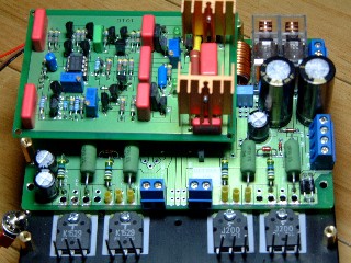
All components on the driver board DT01 , I used the best of them like Philps's 0.1% low noise ,low temperature coefficient resistors ,Wima's MKP and MKS capacitos , best Dual JFETs like NPD5566 or LS844 and IRF's IRF610N, IRF9610. The two black capacitors are Nichicon's MUSE 220uF/100V. The two elays behind MUSE I designed in two Omron 16A/250VAC for larger current output.


I design this Ultra-Low-TIM Amplifier Ultima-1 is for the SACD / DVD-AUDIO Hi-End audio use, the new age of the latest digital sound technology is ready ,everyone should experience the best sound we got, I wish I can make my Advanced Super Audio Amplifier Ultima-1 State-Of-Art ,professional performance, yet DIY's price. MTLIN 2003/01/16
IRF630N / IRF9630 have been changed to Hitachi 2SK214 / 2SJ77 , because of the Ciss of both IRF630N / IRF9630 are too high , and will affect the high frequency response when high power output. 2003/04/19
IRF610/IRF9610 also can be used , see the DT-01 without stand-by circuit . 2003/11/17

AP2 test THD+N 2W at 0.005% total 159W at 0.0386%

AP2 test at 15W FFT Chart
§§ FET Characteristics §§
The FET enjoys certain inherent advantages over bipolar transistors because of the unique
construction and method of operation of the field-effect device. These characteristics include:
★ Low noise
★ No thermal runaway
★ Low distortion and negligible intermodulation ( IM ) products
★ High input impedance at low frequencies
★ Very high dynamic range
★ Zero temperature coefficient Q point
★ Junction capacitance independent of device current